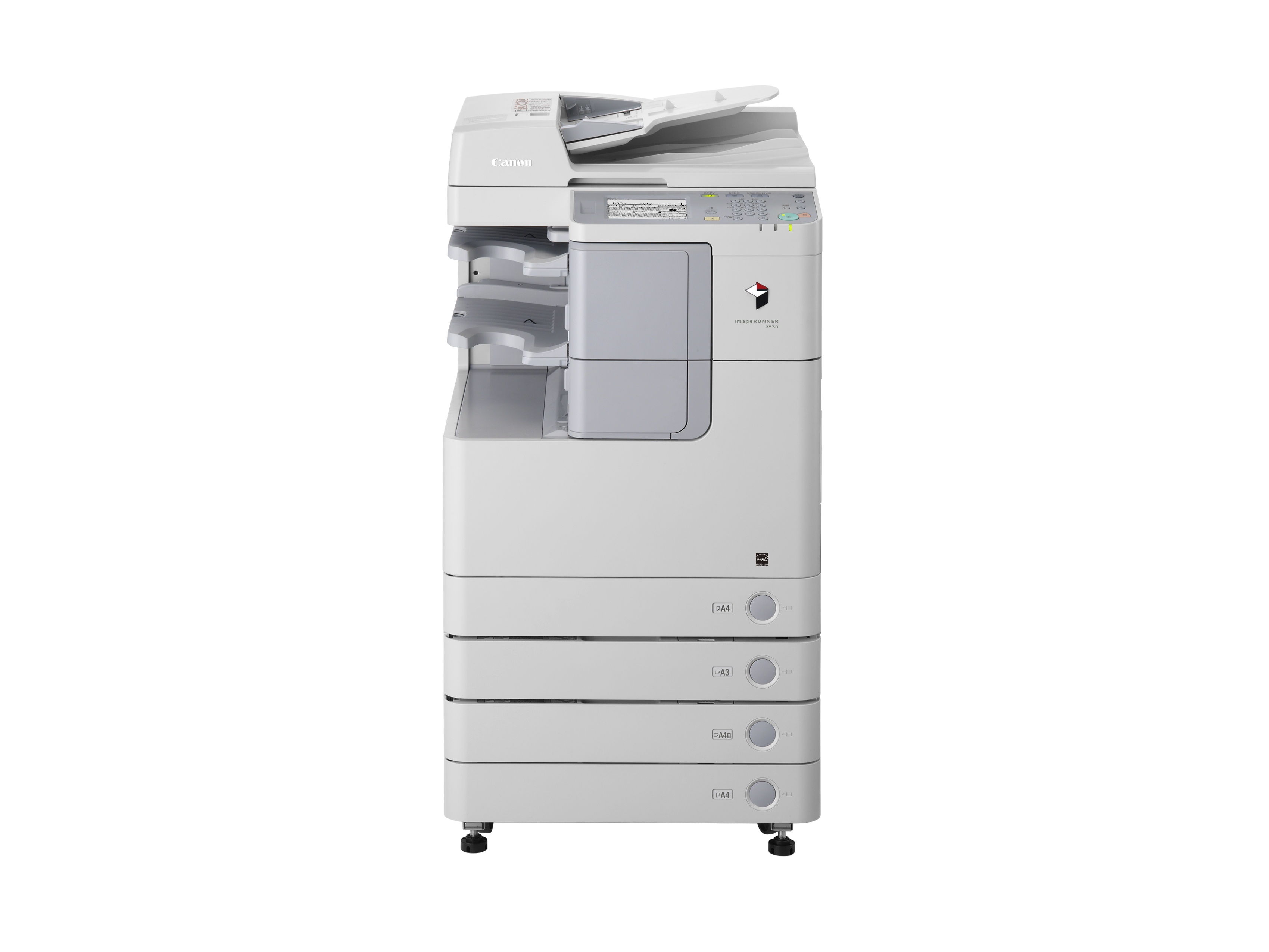
Canon Copier Ir 2530 Service Manual
Service Manual Canon imageRUNNER 2530 imageRUNNER 2525 imageRUNNER 2520 Series, Revision 9.0, 2015 This manual is in the PDF format and have detailed Diagrams, pictures and full procedures to diagnose and repair your Canon imageRUNNER Series copier. You can print, zoom or read any diagram, picture or page from this Service Manual.
Download CANON IMAGERUNNER 2530 2525 2520 SM service manual & repair info for electronics experts Service manuals, schematics, eproms for electrical technicians This site helps you to save the Earth from electronic waste! Canon imageRUNNER-iR 2525 2525i 2530 2530i Service Manual. How to repair/fix Canon imageRUNNER-iR 2525 2525i 2530 2530i Printer. Canon imageRUNNER-iR 2525 Canon.
Every chapter on this manual is fully detailed and contain all the simulation codes, trouble codes, maintenance procedures, reset procedures, diagnose procedures of Canon iR2530 iR2525 iR2520 Series photocopier. You can find easily everything what do you need. To see what contain, please read table of contents: SAFETY PRECAUTIONS Laser Safety Handling of Laser System Turn Power Switch ON Power Supply Safety of Toner About Toner Toner on Clothing or Skin Notes When Handling a Lithium Battery Notes Before Servicing Points to Note at Cleaning Notes On Assembly/Disassembly Notes on Assembly / Disassembly 1. PRODUCT OVERVIEW Product Lineup Host machine Option Features Product feature Specifications Specifications Power consumption Weight / Size Productivity (Print speed) Paper type Name of Parts External View Cross Sectional View (550-sheet 1st cassete model) Cross Sectional View (250-sheet 1st cassette model) Operation Power Switch Control Panel 2. TECHNICAL EXPLANATION Basic Configuration Functional Configuration Basic Sequence Original Exposure System Overview Controls Controller System Overview Controls Contents Laser Exposure System Overview Controls Image Formation System Overview Controls Fixing System Overview Controls Pickup/Feed System Overview Controls Embedded RDS Product Overview E-RDS Setup FAQ Troubleshooting Service cautions 3.
PERIODICAL SERVICE Consumable Parts and Cleaning Parts Cleaning Parts 4.
 2006 Honda CBR1000RR factory repair shop service manual on CD. 2008-2016 Honda CBR1000RR Motorcycle Service Manual: 61MFL08. 1996-2016 Honda CMX250C Rebel 250 Part# 61KEN18 service shop repair manual. 2008-2016 Honda CBR1000RR / CBR1000RA / CBR1000RS Part#. Download 791 Honda Motorcycle PDF manuals. User manuals, Honda Motorcycle Operating guides and Service manuals. Owners Workshop Manual 1983 ATC 250R. Manual 2008 CBR1000RR Fire Blade. Manual CB Hornet 2016. Downloaded an 08-14 Service Manual from a member (thanks JWRUSK). I have modified it so it is searchable and also added bookmarks so it.
. 1326 Answers SOURCE: The erreor code E007 has to do with the fixing.'
y upper film.' y or roller.
Canon Ir 2530 Toner
It is saying that the film is not moving in and out of 'HP' Most of the time it means that the fusing film is torn and not moving properly. If you are getting paper jams in the fusing area and or unfixed or smeared copies. You most likly need to have the fusing film.' y replaced. It could also be that it is out of place and needs to be readjusted. The only problem is that it's a little tricky to get to and not a bad idea to have a new film to replace the old one while you have it out.
Good Luck Posted on Mar 16, 2008. E716 Erroneous communication with optional cassette or 2-way unit 0000 After the presence of a cassette pedestal or a 2-way unit has been detected, the communication fails to be normal for 5 sec.
Check the cable. Replace the DC Controller PCB (PCB4). Replace the Cassette Pedestal Driver PCB. Replace the 2-way unit driver PCB. 0010 When the communication with the 2-way unit is faulty after detecting the connection with the finisher.

Canon Copier User Manual
Install the 2-way unit. Check the cable. Replace the DC Controller PCB (PCB4). Replace the 2-way unit driver PCB. May 20, 2015. E000-0001: Fixing temperature abnormal rise Description: The temperature detected by the main thermistor does not rise to the specified value during startup control. Remedy: - Go through the following to clear the error: CLEAR ENGIN ERRCLR; and then turn OFF and then ON the power.
Check connection of the Connectors (Thermistor Connector and AC Connector). Replace the Fixing Main Thermistor (Film Unit). Replace the Fixing Assembly. Replace the DC Controller PCB (PCB4).
See Service Manual page 173 (7-3): Dec 10, 2013.
Recent Articles
- ✔ Haynes Repair Manual Kawasaki Klr 650
- ✔ Repair Manual 2016dodge Journey
- ✔ Ajcc Cancer Staging Manual 5th Edition Colon
- ✔ Ford Manual 62 Falcon
- ✔ 2011 King Quad 500 Owners Manual
- ✔ Triumph Herald Convertible Owners Manual
- ✔ Nissan Altima 2017 Repair Manual
- ✔ Allison Transmission Mt653 Manual
- ✔ Toyota Hilux 2018 Manuals
- ✔ Haynes Repair Manual Ford Fiesta 2006
- ✔ Onan Quiet Diesel Generator 12500 Operators Manual
- ✔ Hyundai Engine Manual
- ✔ American Standard Acont800 Install Manual
- ✔ Aspen Custom Modeler Examples Guide
- ✔ Leroy Somer Windlass Manual S600
- ✔ Keyboard Manual 2018
- ✔ Landis Focus Axr Manual
- ✔ Webasto Blue Cool Manual
- ✔ Hansen Ap 16 Auto Purger Manual